 Home
HomeHow to Use 360° Equirectangular Panoramas for Greater Realism in Games
For realistic surroundings and convincing real-time effects in games, developers and designers use map textures that convey a very wide or entire view of a scene. In this post, we are primarily referring to two main spherical image formats: equirectangular panorama and cubemap. We would like to share some tips and tricks for solving typical problems while projecting a panorama onto a cube.
Equirectangular Panorama and Cubic Format
Panoramic projections are used to map a full or partial 3D scene onto a 2-dimensional surface. For example, cylindrical projections convey the scene visible in all directions, except for right above the viewer’s head and under their feet. This means that the top and bottom of the imaginary cylinder will be missing in such map images when they are ‘wrapped.’
Unlike cylindrical views, spherical panoramas incorporate a 180° vertical viewing angle and a 360° horizontal viewing angle. They contain light data originating from all directions, and therefore can be visualized as comprising the points on a sphere. This format has become popular in social media and marketing and has found application in 3D graphics programs, simulations of interiors, immersive panoramic movies, and computer and video games.
An equirectangular panorama consists of a single rectangular image whose width and height correlate as 2:1.
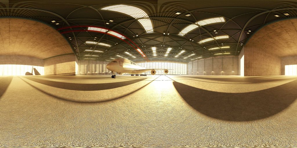
Such images can be captured with a 360-degree camera or using “cheap and dirty” methods like this. (Images with a single spherically distorted texture can be instantly tested here.)
The cubic format/cubemap uses six cube faces to fill the whole sphere around the viewer. These maps are often created by imaging the scene with six 90-degree FoV cameras giving a left, front, right, back, top, and bottom texture. The six images are typically arranged as an unfolded cube (‘horizontal cross’).
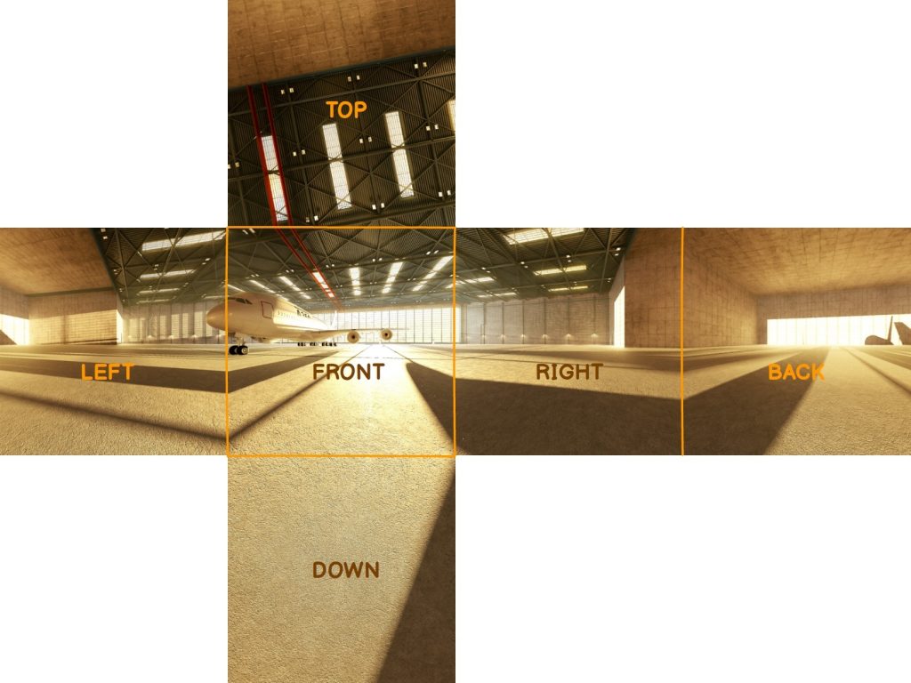
Each of the cubemap faces has an appropriate texture map. When folded, the view is remapped to the faces of a cube which fit seamlessly.
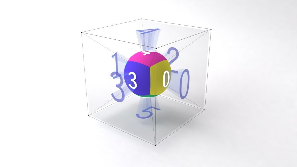
On one hand, a cubemap is a kind of surface texture, like an ordinary 2D texture. On the other hand, it is volumetric because every point within the 3D texture coordinate space corresponds to the face of the cube it comes closest to:
Why Convert Equirectangular to Cubemaps?
Converting an equirectangular image into a cubemap is most commonly used for some navigable virtual environment solutions or when editing the north and south poles of spherical panoramas.
Equirectangular images are stretched in the ‘latitude’ direction. It is the reason for a considerable amount of data redundancy near the poles. When downsizing an image in an editor, the effective texture resolution is decreased as expected – except near the poles. This can cause radial artifacts when viewed later in panorama viewers. (An equirectangular projection is thus suitable for simulating only those environments where the distortions of the texture at the top and bottom of the sphere are negligible.)
A solution is to switch to a less distorted projection before scaling, blurring or sharpening a panorama, and to switch back later if necessary. A cubemap provides such a projection.
The cubemap method found another application in real-time computer graphics. Environment mapping, or rather sphere mapping, is employed for making objects appear shiny or reflective. In that case, the map texture should be a view of the scene as reflected in a shiny ball.
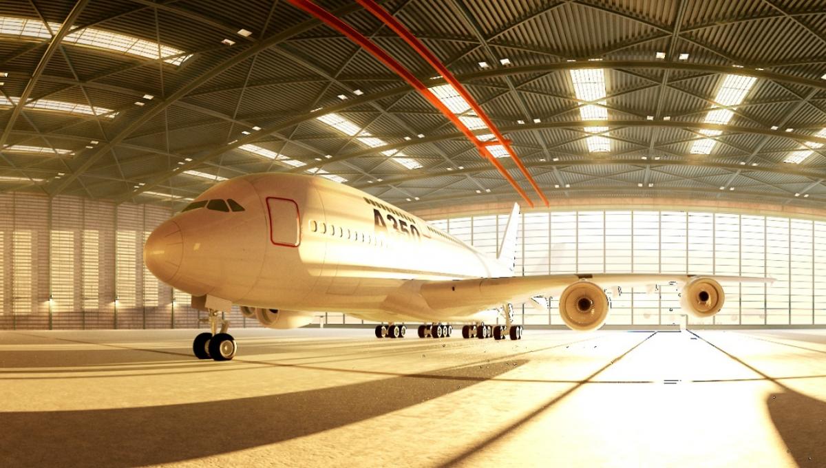
The format enables video game developers and designers to add rich not-explorable environments to a game at a minimal performance cost. The method they use is called skybox. Photographs, hand-drawn images, or pre-rendered 3D geometry that present the background and unreachable objects can be used as texture for a skybox. The graphical engine renders the images as faces of a cube at a practically infinite distance from the viewpoint located in the center of the cube. The perspective projection reduces the effects of projecting the environment to create the cubemap. As a result, the viewer experiences an illusion of being surrounded by the scene which was used to generate the skybox.
Ways to Make a Cubemap
One of the ways to convert panorama to cubemap is to use Unity’s built-in Skybox feature and render an image via a skybox material.
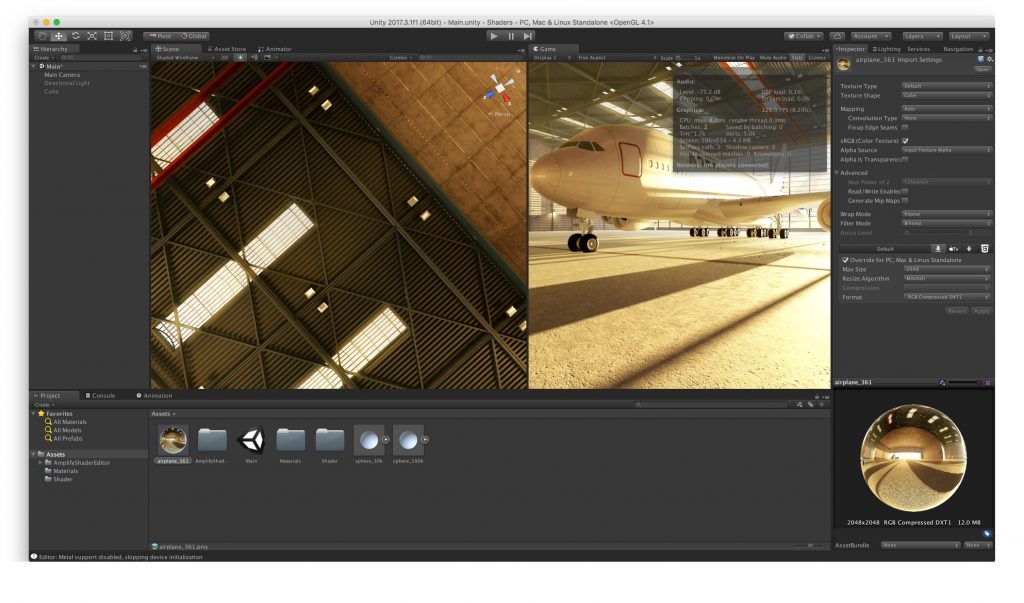
1. First, get a panoramic image and drag it into Unity.
2. Set the texture import settings to match the type of the panoramic projection. Select Advanced (not ‘cubemap,’ even if you have a cubemap). For a cylindrical image choose the Latitude-Longitude Layout (Cylindrical) and set the texture size as 4096. If you have a single cubemap image, choose the mapping as ‘6 Frames Layout (Cubic Environment)’. If your cubemap is comprised of 6 separate images, import each one as a standard texture, and make sure to set the Wrap mode to ‘clamp’ to prevent seam lines.
3. Create a Material for the texture. Create a new material, and for the shader choose ‘skybox/cubemap’ and drag the texture onto the material. If you are using six separate images, choose ‘skybox/6 sided’ and drag each image onto the matching property.
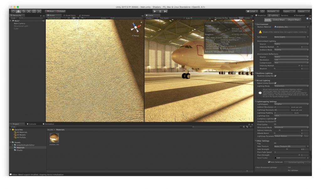
4. Add the Material to the Scene’s Skybox. Open the Scene’s Lighting settings (via the menu Window -> Lighting -> Scene tab). At the top, under Environmental Lighting, drag the Material onto the Skybox property.
5. Done! Set the project to VR mode in Player Settings, click on ‘Play’ in the Editor, and view the panorama.
The benefit of this feature is that neither meshes nor writing any code are required. You can quickly add the image to your scene. Cubemaps will show seams along the edges of the cube if they aren’t mapped properly. When a cubemap is rendered automatically in graphics hardware by a game engine, it will be seamless because it uses the Clamp UV address mode.
Another way is to use a ‘Panorama To Cubemap’ script. It is available at Unity Asset Store for free. The plugin allows for deployment of equirectangular images onto six cubemap images via Unity. Users drag and drop an equirectangular panorama into the wizard and generate a skybox automatically. (However, it can’t be done in real-time/play mode, which is a considerable drawback).
The script also works great for creating and updating reflection maps. It allows for quick iterations of cubemap tweaking to and from Photoshop without duplicating the assets. Developers can replace a texture resolution they don’t use (64, 128) with more useful resolutions (2048, 4096) in PanoramaToCubemap.cs at lines 26, 129 and 132. 4096 are created but used as 2048 (Unity default); developers need to select them in output_images and change Max Size to 4096.
Here are some other tools that may come in handy for converting equirectangular to the cubemap format, especially in indie design or while prototyping and doing trial-and-error work.
- 360Toolkit is an online set of fast and easy-to-use tools for converting equirectangular to cubemap and vice versa, previewing panoramas, and tagging photos for Facebook. Equirectangular pictures can be converted into all known types of cubemaps and previewed instantly without any upload.
- Bixorama is a Windows desktop app for converting, modifying, generating, previewing and publishing 360° photos. You can temporarily convert equirectangular images to six cube faces for easy painting.
- Equi2cubic is a simple MATLAB script that takes an equirectangular version of a scene and creates six faces of a cube representing the scene.
- equirect-cubemap-faces-js converts an equirectangular map into an array of cubemap faces (like those sent to OpenGL).
- Pano2VR сonverts 8-bit panoramas. Load a panorama in Pano2VR, press the ‘Convert input’ button and select the output images format you want.
- Panorama Converter is a simple tool for converting a panorama image into cubemap sides. You can save the result as a cubemap horizontal layout, ZIP archive with separate image sides, or ZIP archive with output images for a further compression with ATF converter.
- Panorama To Cubemap is a web app which converts an equirectangular panorama to six cube faces. It runs in your browser by using the Canvas API to manipulate image data, uses Lanczos interpolation for high-quality output, and allows rotating the cubemap to control the scene orientation.
- Qbit outputs six images using equirectangular projection, one for each face of a skybox. Any modern 3D game engine can use the images.
Unity Specific Tips and Tricks
In our projects, we prefer not to convert panorama to cubemap as an interim step. We have found out that it is better to apply an equirectangular map texture directly to a skybox or skydome. There are several reasons for that.
Although Unity generally works great with cubemaps, developers have to deal with certain issues:
1. Artifacts: In most cases, when an equirectangular projection is ’unwrapped’, the sphere has top and/or bottom artifacts. Even the increased number of polygons does not ensure proper quality.
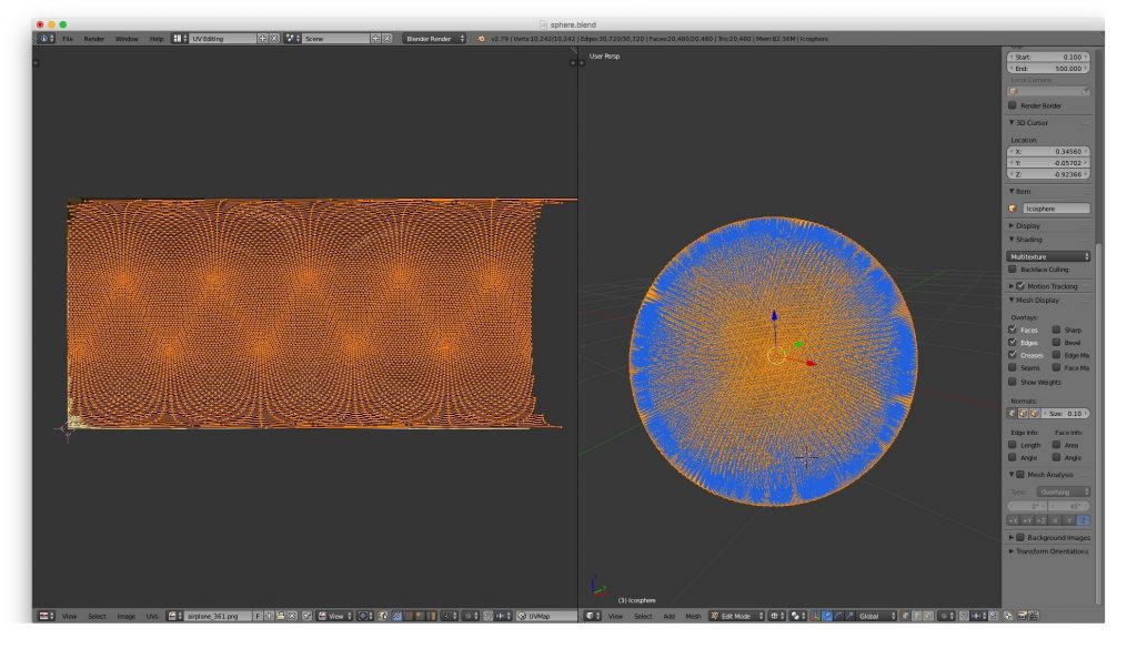
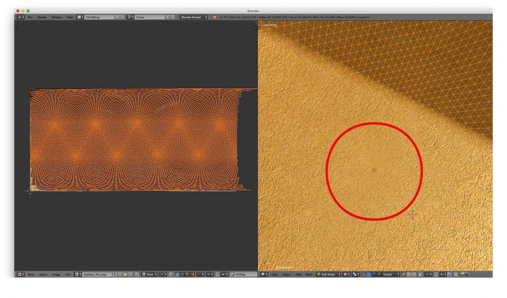
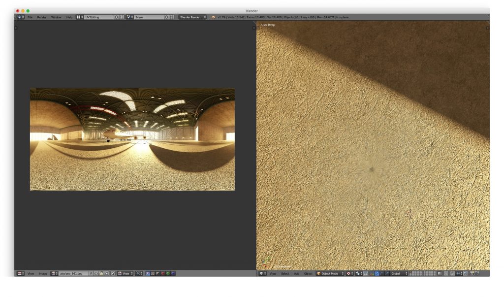
2. The mesh is too fine. When the ‘unwrapped’ spherical projection has too many polygons, it is difficult to apply, while even 40K-50K vertices do not ensure proper texture quality at the top and bottom. And since in most cases a skybox is used, it is an issue.
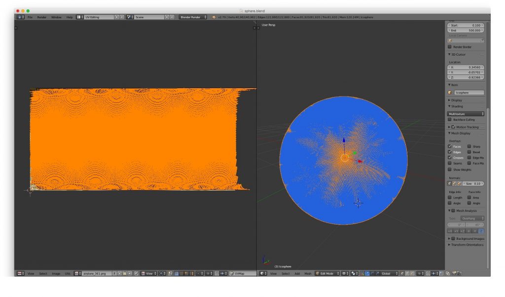
3. Unity’s default Skybox functionality in an empty scene has 5K vertices. The number is superfluous.
4. If the skybox is baked (i.e. fixed) not at the viewer’s height, the viewer does not feel ‘present’ in the virtual reality, especially in indoor interiors. To feel natural, the central position of the imaginary camera within the sphere must be lowered to the average human eye-level, i.e. rather close to the ground in a skybox.
To solve these problems, a certain shader needs to be written. We can do it in two ways:
I. Custom Shaders
Here is a manually written shader for Unity:
Shader “#Custom/360Cube” {
Properties {
_MainTex(“Main texture (RGB)”, 2D) = “white” {}
_Rotation(“Rotation”, float) = -90
}
SubShader {
Tags { “Queue”=”Background” “RenderType”=”Background”}
Cull Off ZWrite On
Pass {
ZTest Always Cull Off ZWrite On
Fog { Mode off }
CGPROGRAM
#pragma vertex vert
#pragma fragment frag
#include “UnityCG.cginc”
sampler2D _MainTex;
float4 _MainTex_ST;
float _Rotation;
struct appdata_t {
float4 vertex : POSITION;
};
struct v2f {
float4 vertex : SV_POSITION;
float3 texcoord : TEXCOORD0;
};
v2f vert (appdata_t v)
{
v2f o;
o.vertex = UnityObjectToClipPos(v.vertex);
o.texcoord = v.vertex.xyz ;
float s = sin ( (_Rotation / 180) * UNITY_PI);
float c = cos ( (_Rotation / 180) * UNITY_PI );
float2x2 rotationMatrix = float2x2( c, -s, s, c) ;
rotationMatrix *=0.5;
rotationMatrix +=0.5;
rotationMatrix = rotationMatrix * 2-1;
o.texcoord.xz = mul ( o.texcoord.xz, rotationMatrix );
return o;
}
fixed4 frag (v2f i) : SV_Target
{
float3 dir = normalize(i.texcoord);
float2 longlat = float2(atan2(dir.x , dir.z), acos(-dir.y)) ;
float2 uv = longlat / float2(2.0 * UNITY_PI, UNITY_PI);
uv.x += 0.5;
half4 tex = tex2D (_MainTex, TRANSFORM_TEX(uv, _MainTex));
return tex;
}
ENDCG
}
}
Fallback Off
}
We wrote another one for the web-based application, where a GLSL shader is needed. It may be useful as an example for ThreeJS, A-Frame, etc.:
GLSL Language
Vertex Shader:
uniform float uv_rotation;
varying vec3 vTexCoord;
const float pi = 3.141592653589793238462643383279502884197169;
void main() {
float s = sin ( (uv_rotation / 180.0) * pi);
float c = cos ( (uv_rotation / 180.0) * pi);
mat2 rotationMatrix = mat2( c, -s, s, c) ;
rotationMatrix *= 0.5;
rotationMatrix += 0.5;
rotationMatrix = rotationMatrix * 2.0 – 1.0;
vTexCoord = position;
vTexCoord.xz = position.xz * rotationMatrix;
gl_Position = projectionMatrix * modelViewMatrix * vec4(position, 1.0);
}
Fragment Shader:
uniform sampler2D src;
const float pi = 3.141592653589793238462643383279502884197169;
varying vec3 vTexCoord;
void main() {
vec3 direction = normalize(vTexCoord);
vec2 longlat = vec2(atan(direction.z, direction.x), acos(-direction.y)) ;
vec2 uv = longlat / vec2(2.0 * pi, pi);
uv.x += 0.5;
vec4 tex = texture2D(src, uv);
gl_FragColor = tex;’,
}
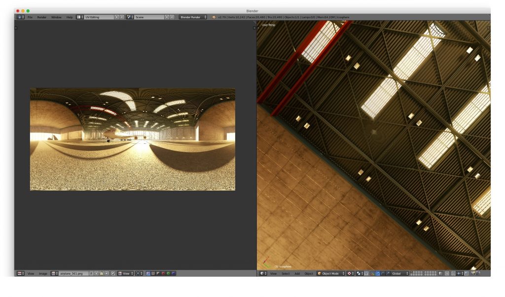
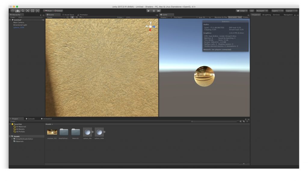
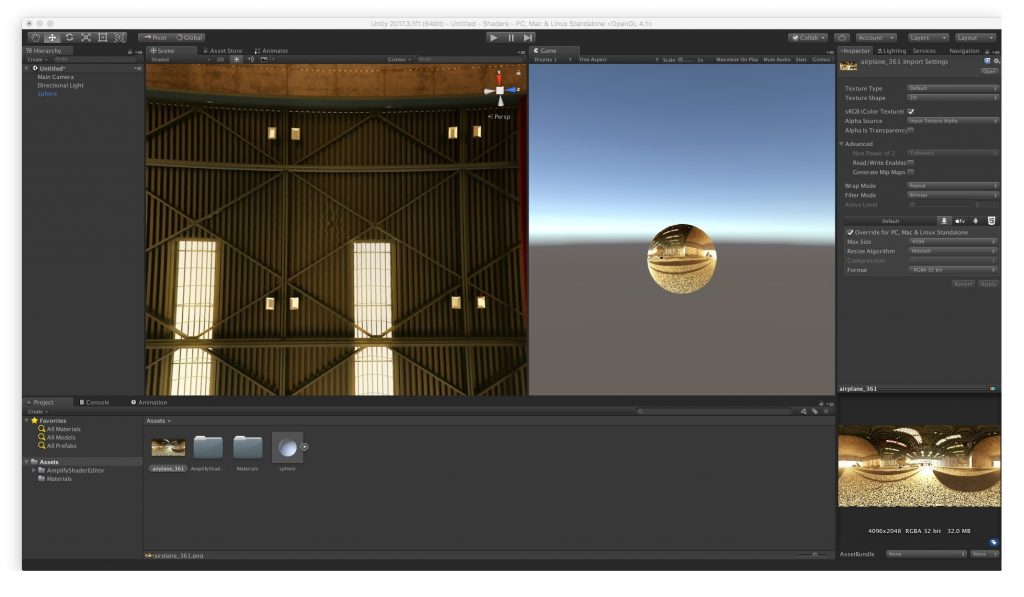
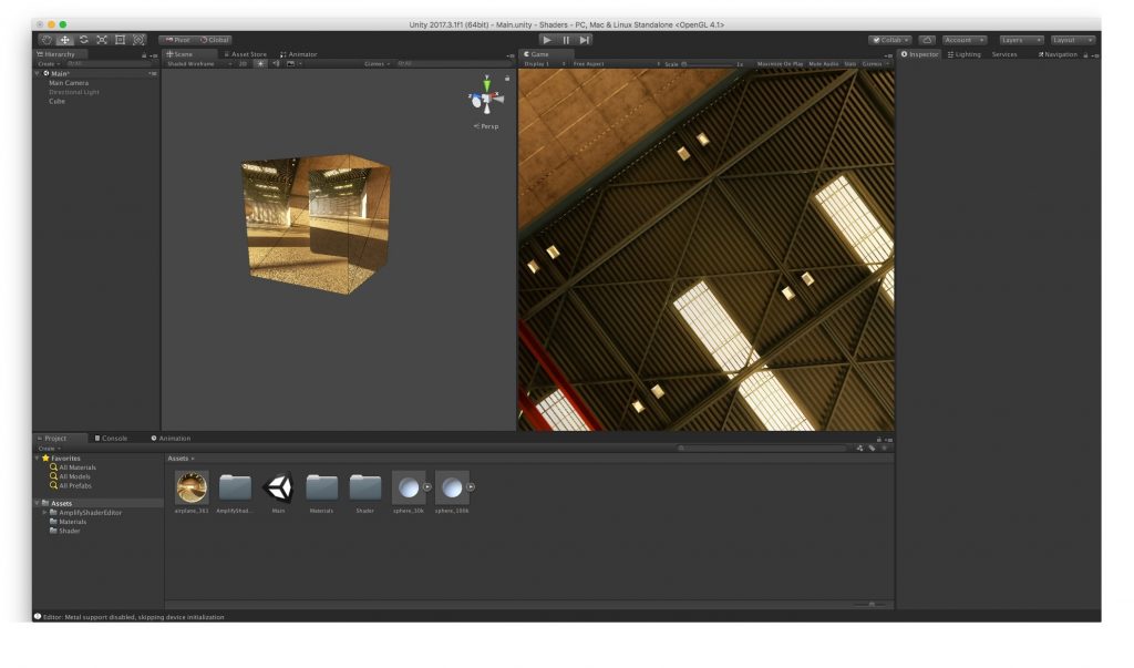
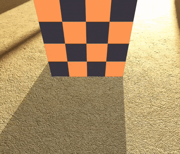
This shader does not require any unwrapping and can be used with any geometry. The picture below shows it applied to a cube.
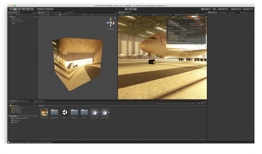
If we compare the default Unity shader and the unwrapped sphere, a cube looks more optimized. A cube’s 28 vertices provide sound quality, while the default Unity skybox does not achieve the excellence you’d expect from its 5K vertices. Moreover, no artifacts are noticeable at the cube’s top and bottom. The unwrapped sphere’s 40K-50K polygons fail at providing good quality altogether.
These are the solutions to problems 1-3 listed above. Let’s take a look at issue #4.
II. Node-based Shader (Amplify Shader Editor in Unity)
The node-based shader is rather similar to the manually written shader described above. However, it helps make the floor/ground closer to the viewer while saving the solutions to problems 1-3.
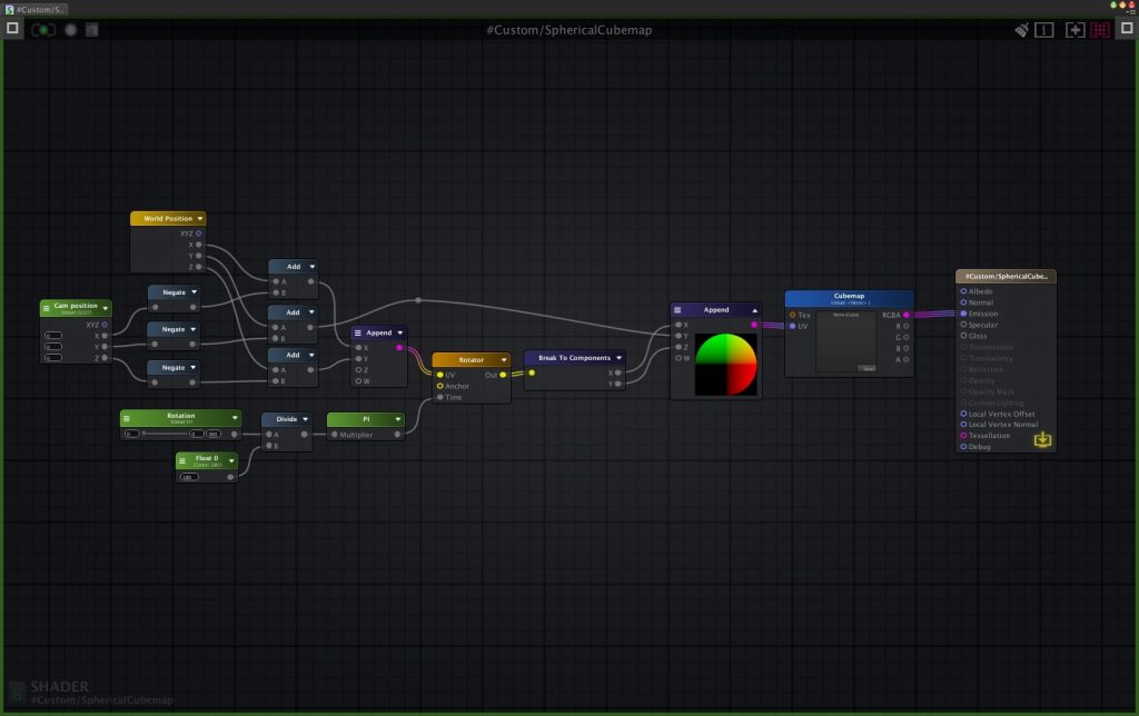
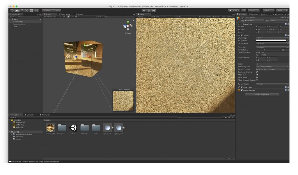
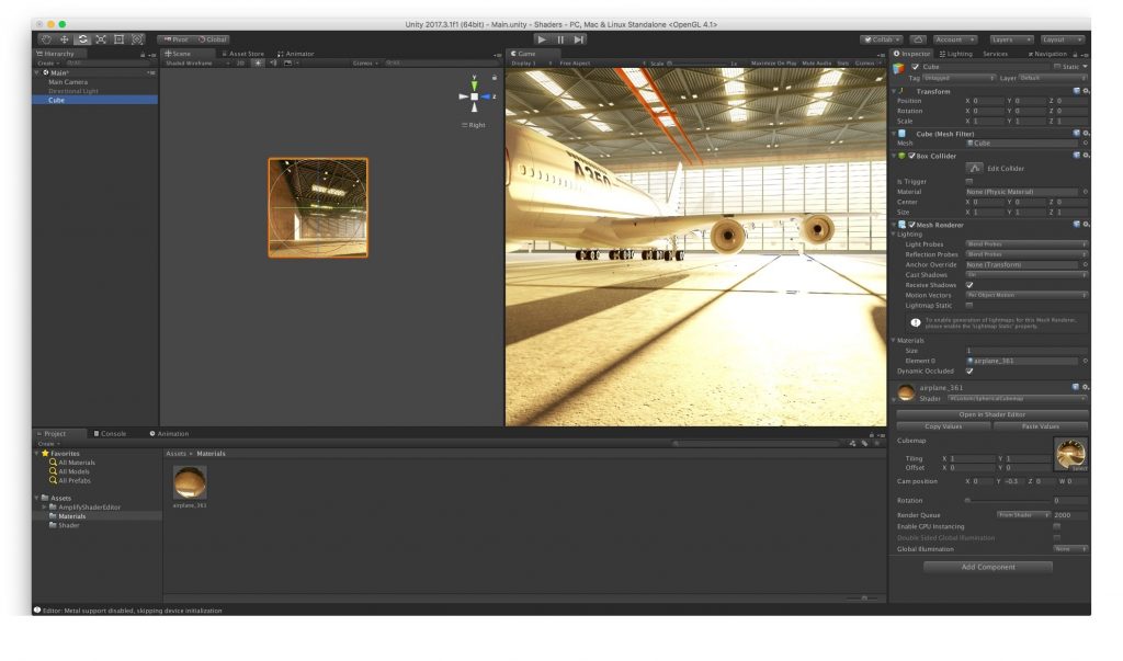
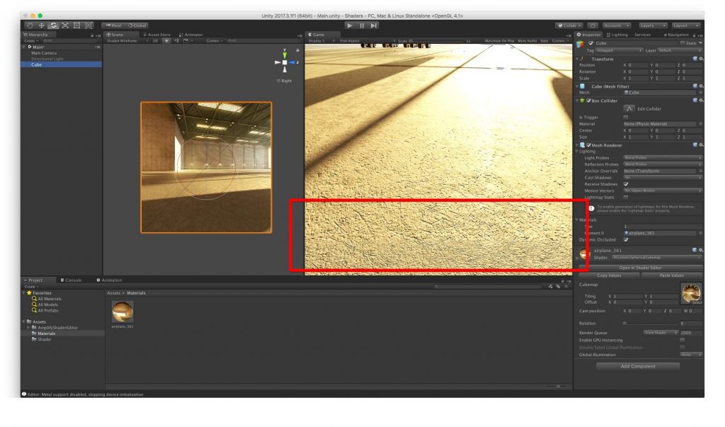
To move the viewpoint closer to the virtual floor, we must be able to shift the projection on the cube too. The camera position node is responsible for this. Here is what it looks like:
The camera was moved by -0.3 in the Y axis (We chose this parameter randomly, but it should be configured for each VR case individually). We should also change the center of the projection in the shader:
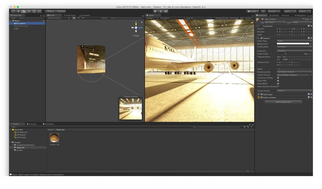
If we don’t do it, the projection will give the illusion of looking up from the floor level:
The short animation illustrates the use of the node-based shader:
To Recap
Cube mapping is a method of environment mapping that is used to create pre-rendered panoramic sky and landscape images. The graphical engine then renders the images and projects them onto the faces of a cube. The cubemap method thus helps game developers create realistic game level scenes with an illusion of distant three-dimensional surroundings. It is also the easiest and fastest way to render reflections in real-time computer graphics.
Content created by our partner, Onix-systems.